(Not
for the Purist and only if you’ve got 12V electric)
Introduction
This
document describes an electronic ignition for Indians. The trigger unit fits
into a standard Autolite distributor and does not interfere with the manual
advance and retard control used on Indians.
For
reliability reasons most of the components are commercially available electronic
ignition components from an ignition system produced by Bosch in the 70s and 80s
and used in many European cars (Volkswagen, Ford) and motorbikes (BMW). Therefore, most of the parts required can be found at a breakers yard.
Using those commercial products however requires that we have a 12V electric on
our Indian, which I achieved by using a 170W 12V Bosch generator from a beetle
that has exactly the same dimensions than the original Autolite 6V generator. As the components are readily available there is no electronic skill
required in wiring it up. However, the production of the actuator requires some
mechanical skills and the use of a lathe.
Working
Principle
The
ignition uses a “Hall Sensor” instead of mechanical contact breakers. This
hall sensor is an electronic device that detects the presence of a metal vane
passing through the gap between a magnet and the sensor. It not being an optical
or mechanical sensor makes it extremely robust against dirt, moisture and oil.
The electric signal from the hall sensor is delivered to the “Ignition Control
Unit”. This control unit switches the current to the ignition coil. The
switching is done much faster than with a mechanical breaker. Therefore, the
ignition coil produces extremely high voltages, independent on the engine speed.
Parts
Required
Most
of the parts are available from a good breakers yard, and can be salvaged out of
an old hall sensor distributor. Where known I give component numbers from
possible suppliers. Some of the
parts are available from electronic components suppliers. As I’ve used RS and
they have an almost world wide coverage, I will give the RS order number (where
available)
1
Ignition Trigger Unit - Bosch 0227 100 123, Siemens 5WK6 101
Volkswagen
211 905 351E
1
Hall Sensor - Salvage or RS 178-5689
1
Ignition Coil* WC 0221 600 016 (yellow label)
1
1Ω 100W
Resistor** RS 188 087
Some
cable
Some
crimp connectors
1
Actuator - Home made
*Bosch
distinguishes the different ignition coils by the color of the label. The
ignition coil that is suitable for the hall sensor ignition MUST have a yellow
label. Ignition coils with blue (breaker point ignition) and green (more modern
electronic ignition) will destroy the ignition trigger unit.
**In
the car, where the ignition comes from this resistor it is not obviously
present. It consists normally of a resistance cable as part of the wiring loom.
(I have tried a cheaper 50W version of this resistor and fried it!)
The
Actuator and Distributor Modifications
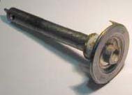
The
actuator looks like the end of a tin cup and should be made from low carbon
steel (better in conducting the magnetic field). The top should be formed in a
way that the original distributor finger can be installed into the distributor
case. Diameter of the actuator should be 40 mm.
The
sides of the actuator are two approximately 10-mm long and 25 mm wide vanes with
the resulting gaps. Rotation of the actuator is clockwise with half the engine
revs. The ignition coil receives
current whilst the metal vane is passing through the magnetic field of the hall
sensor. And is switched off (ignition point) when the vane leaves the sensor.
To
achieve the correct ignition points for both cylinders on our 42° V-twin
the ignition point for the front
cylinder has to be 201° after
the ignition of the rear cylinder ( 180° for
the opposing working cycle plus half of the 42° difference
to compensate for the V of the cylinders. On a parallel twin or boxer the
ignition would be evenly spaced at 180°)
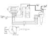
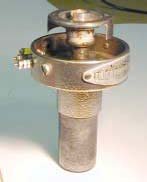
A
schematic of the actuator principle can be seen in Figure 1 (wiring diagram and
actuator details). My actual actuator unit is shown in Figure 4 (The actuator)
and Figure 3 (The complete assembly with the part removed actuator).
The
notch for the distributor finger must ensure that the finger is pointing towards
the corresponding pick up on the distributor cap, when the vane passes through
the ignition point (see Timing of the Ignition)
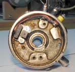
The
hall sensor is fitted into the distributor body so that the vanes of the
actuator pass through the gap of the magnetic field without touching the sensor
body. The cables are lead through to a three feed of a similar make to the one
already there for the breaker connection. The installed hall sensor can be seen
in Figure 2 (Position of hall sensor).
Wiring
it up
The
wiring should be done in good quality automotive cables. The cables between the
hall sensor and the ignition control unit have to carry almost no current (TTL
signal) and therefore can be rather thin. The sensor cable will probably run
parallel to the ignition cable and therefore should be screened. The screen
should be connected to ground.
The
power supply cable to the ignition control unit and to the ignition coil should
be at least 0.75 mm2,
I would use 1.5 mm2.
The
ignition control unit dissipates quite some heat. To prevent it from overheating
it should be installed on a large piece of metal (e.g. inside the toolbox or
between the tank). Before fitting it, one should apply heat conductive paste
between the unit and the metal.
The
ignition coil for the hall sensor ignition operates at only 9 Volts. Therefore,
the 1Ω resistor
has to be fitted in line. Not doing so will result in the death of the ignition
trigger unit and or the ignition coil. This 1Ω resistor
is normally a resistance cable, but for ease of use is in this case replaced
with a 100W metal case resistor.
For
easy assembly I fitted two more “feed through” on the distributor case,
similar to the one already used by the breaker points. Onto these, I connect the
signal cable using crimp rings. The connector on the ignition control unit uses
3.5 mm flat crimp connectors, the ignition coil uses 6mm crimps. To toughen the
connections I have used heat shrink tube around the shaft of all crimp
connectors.
Timing
of the Ignition
The
timing point is when the vane of the actuator is passing a point that is 1 mm
behind the center of the hall sensor (in rotation direction). The rest of the
timing is done as with a contact breaker ignition.
WARNING
An
electronic ignition produces extremely high voltages of approximately 30 000
Volts (mechanical ignition 15-20000Volt). Those voltages can be lethal.
Therefore, considerable care has to be taken when working on electronic ignition
components. Never touch any bare
wires on the high voltage side of the ignition without ensuring that the battery
is disconnected and the wire has been grounded. Ensure that you use high quality
and in perfect condition ignition leads and safe spark plug caps.
Disclaimer: Every
one wanting to re produce the electronic ignition described here does so
entirely on his/her own responsibility. I accept no responsibility on injury
caused or for the correctness of the given information.
Figures
| Figure
1 (wiring diagram and actuator details)
|
Figure
2 (Position of hall sensor)
|
Figure
3 (The complete assembly with the part removed actuator)
|
Figure
4 (The actuator)
|
Frank Nuber